Steady Flow Processes
- Engineering

- Nov 30, 2020
- 4 min read
Updated: Feb 2, 2021
In this notes sheet:
The basic form of the first law, ΔQ – ΔW = ΔE, only applies to closed systems - no mass can transfer across the system boundary, only energy in the form of heat and work.
In reality, perfectly closed systems are quite rare (take a turbine, for example: air flows in as well as heat, shaft work and hot air flow out), and as such a different model is required:
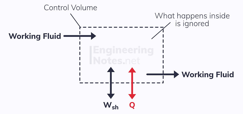
The energy transfers across the control volume surface are:
Shaft work
Heat transfer
Energy in the working fluid (kinetic, potential, and internal energies)
To simplify the process, we only look at the energy inputs and outputs: what goes on inside the control volume is irrelevant.
We call where the working fluid enters and exits ports.
The control volume above has two ports: one inflow and one outflow port.
The Steady Flow Energy Equation (SFEE)
In order to solve problems involving steady flow through a control volume, we use the Steady Flow Energy Equation (SFEE) instead of the simple first law equation:
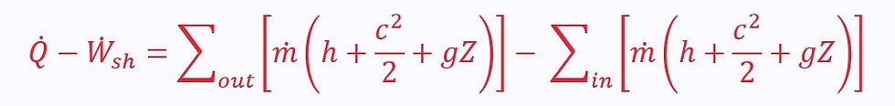
In a less mathematically intimidating form:
Left hand side: rate of energy transfer – rate of shaft work
Right hand side: sum of output mass energy flow rates – sum of input mass energy flow rates
Note: The dot above the letters means it is a rate of change with respect to time:

Thankfully, kinetic and potential energies can often be ignored, simplifying the equation immensely. However, it is important you start with the above form when solving problems, else you will likely forget parts.
See the derivation of the SFEE here
Mass Continuity Equation
We can use the SFEE in conjunction with the principle of conservation of mass. This means that the mass in the control volume must stay constant, so the total input mass flow rate = total output mass flow rate:

Therefore, for a two-port control volume where potential energies are negligible, the SFEE reduces to:

When kinetic energy too can be ignored, it becomes:

The point is, the SFEE in its full form may look difficult, but it really isn’t. Just be neat and methodical in your workings, and always start from the full form and then see which terms you can set to zero.
Applications of the SFEE
There are a number of very common examples where the SFEE is applied and simplified. These are worth knowing, as crop up in almost all problems involving steady flow.
This is also where some actual real-life engineering gets involved. Which is fun.
Each example has a standard block diagram symbol. These should be learned as they are used to describe multi-stage processes like the Rankine Cycle (see below).
Partly Closed Valve (Throttling)
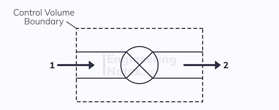
This is the simplest form every term in the SFEE other than the enthalpies are negligible:
Heat transfer is negligible when the valve is well insulated
There is no shaft work
Kinetic energy change is negligible
Potential energy change is negligible
There are two ports, so the SFEE reduces to:

From this you can see that throttling (the process that takes place in a partly-closed valve) is isenthalpic.
Nozzles
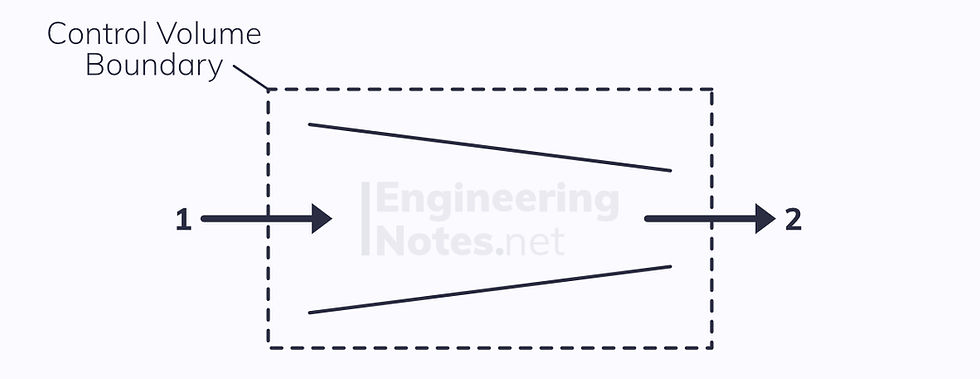
A simple nozzle can be modelled as a duct of reducing cross-sectional area, used to increase the kinetic energy of the working fluid at the expense of its enthalpy.
There is no heat transfer to or from the working fluid
There is no shaft work
There is a massive change in kinetic energy
Potential energy is negligible
Again, there are two ports, so the SFEE becomes:

Boilers
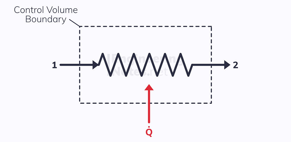
Heat is transferred to the working fluid to the point of saturation, and the fluid evaporates.
Boilers are isobaric, meaning there is no work done.
Kinetic energy is negligible
Potential energy is negligible
There are two ports, so the SFEE reduces to:

Pumps & Compressors

Pumps and compressors are exactly the same thing: the only difference is that a pump refers to a liquid and a compressor refers to a gas (as liquids are generally incompressible).
There is typically no heat transfer – the process is adiabatic
There is a pressure change, so there is shaft work
Kinetic energy and potential energy can sometimes be ignored, but not always
When KE and PE are negligible, the SFEE reduces to:

If KE and PE are not negligible (e.g. pumping water up a hill), the SFEE becomes:

Where v is the specific volume. In this instance, specific work is given by vΔP, not PΔv.
Turbines

The opposite of a pump or compressor, the working fluid expands in a turbine to provide shaft work.
Heat transfer is generally negligible
There is a lot of output shaft work (h₁ > h₂, so W > 0)
Kinetic energy is sometimes negligible, but often not
Potential energy can usually be ignored
Two ports, so the SFEE becomes:

Heat Exchanger
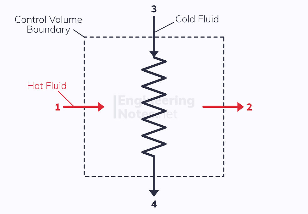
A heat exchanger (as its name suggests) transfers heat from one working fluid to another. This means that if we make the control volume the whole exchanger with four ports, there is no net heat transfer.
Obviously, there is also no shaft work or change in kinetic and potential energy. Therefore:

Using mass continuity equations for ports 1 & 2 and 3 & 4, we can simplify the SFEE even further to:

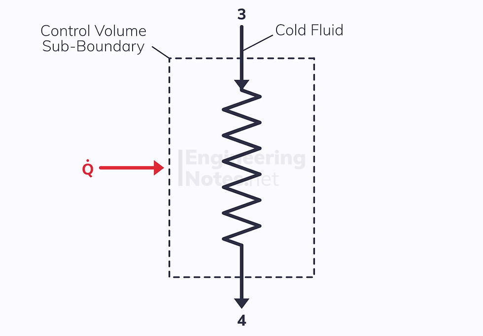
However, if we make the control volume just one of the two fluids with a positive or negative heat transfer from the other fluid, there are two ports and there is a heat transfer:

Where the heat transfer comes from the hot stream:

Mixing Chamber

A typical mixing chamber has two inflow ports and one outflow port, though there could be many more inflow ports.
There is no net heat transfer between the control volume and its surroundings (there may be a heat transfer between the mixing fluids, but this is inside the boundaries so irrelevant)
There is no shaft work
KE and PE are both negligible
The only remaining factors are enthalpy and flow rates:

Using mass continuity, we know that:

Mass & Volume Flow Rates
The mass flow rate can be calculated from the velocity and density of the working fluid, and the size of the duct/pipe it is flowing through:

ρ is the density of the working fluid
C is the velocity
A is the area of the duct/pipe
From this, we can calculate the volume flow rate:

Combining these, and using specific volume gives us the most useful form:

The Rankine Cycle
First put forward by William Rankine in 1859, the Rankine Cycle models the performance of steam turbine systems:
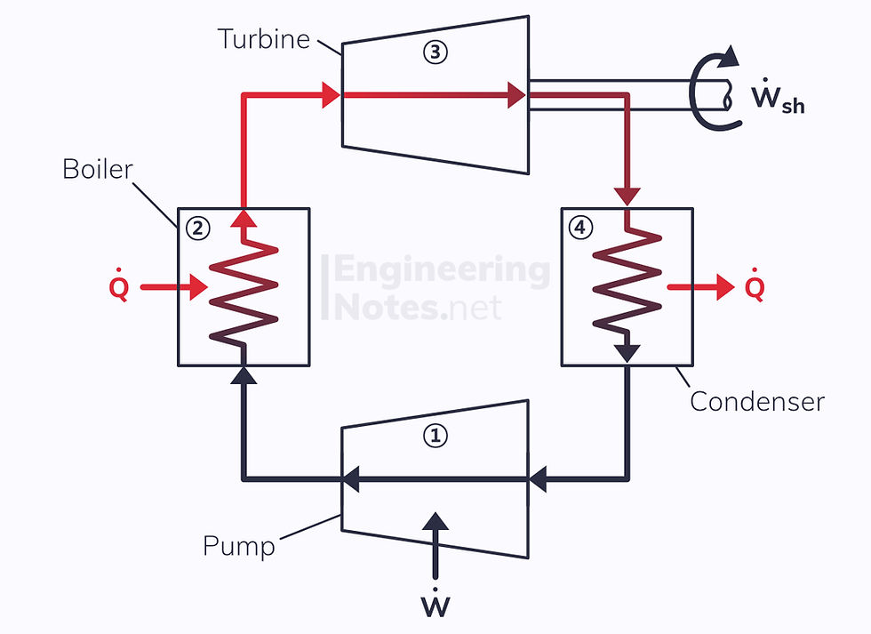
1. Cold liquid is pressurised in the pump
2. Pressurised liquid is heated in the boiler (isobaric process) and vaporises
3. Vapour expands in the turbine as temperature and pressure reduce; dryness fraction decreases from 1 to inside the vapour-dome
4. Wet vapour condenses at constant pressure to become a saturated liquid


Comments