Internal Flows
- Engineering

- Nov 28, 2020
- 4 min read
Updated: May 19, 2021
In this notes sheet...
An internal flow is any flow that is fully enclosed by fixed surfaces, and is predominantly determined by the viscous forces at the surfaces. The most common example is pipe flow.
As flow enters a pipe, you can see the effect of the viscous force coming into play:
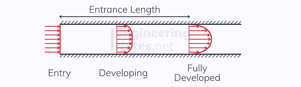
Initially, before the fluid enters the pipe, the flow is inviscid: the velocity field is uniform.
Throughout the entrance length, the velocity decreases closer to the surfaces.
The flow is fully developed in a constant velocity field, with zero relative velocity at the boundaries (no-slip condition).
The entrance length is defined as the length of pipe for the flow to fully develop.
Fully Developed Laminar Flow
The most general form of this is between two flat, parallel, infinite plates:
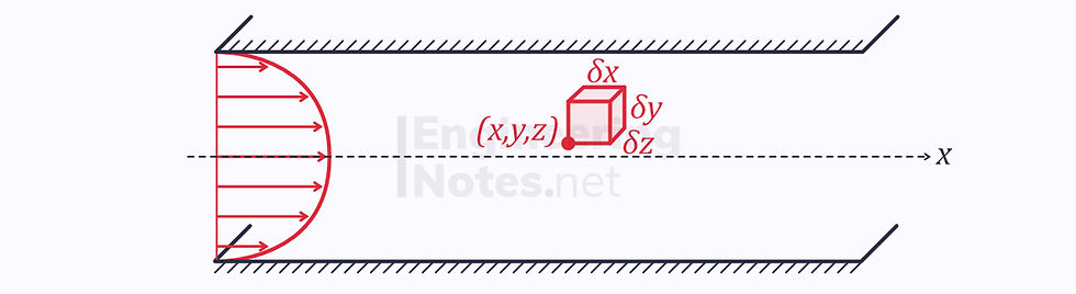
In laminar flow, all velocities are parallel to the net direction of flow.
Taking the infinitely small fluid particle above, we can apply conservation of momentum to the horizontal forces acting on in:

The left and right forces in grey are pressure forces
The top and bottom forces in red are viscous forces
We do not know the directions of these, only that they point in opposite directions
The Following Steps show how to derive the velocity profile for fully developed laminar flow between two infinite plates, but the same steps should be followed to derive any similar velocity profile.
Pressure Forces
Pressure force on the left:

Difference in pressure over distance δx:

Pressure force on the right:


Viscous Forces
We know that the viscous force is given as:

Therefore, bottom viscous force is given as:

The velocity on the top surface is given as:

So, the top viscous force is:

We know that the top viscous force must be positive, and te bottom force negative (see notes sheet on force in fluids).
Newton’s First Law & Conservation of Momentum
Since the velocity is independent of x-position in laminar flow, there is no change in velocity in this direction. This means there is no net horizontal force acting on the particle, so all the forces must cancel out:
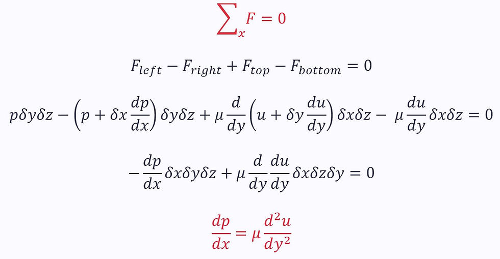
Both parts of the equation must be equal to the same constant then:

Integrating the first of these over a pipe length L:

Plugging this into the second equation:
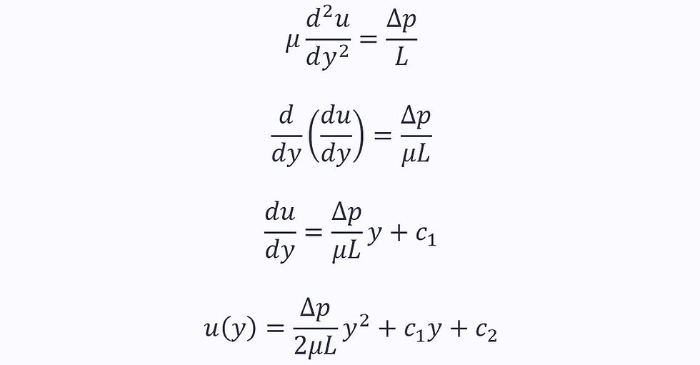
Substituting in the boundary conditions from the no-slip condition:

This is the velocity profile for laminar, fully developed flow between to infinite, parallel plates.
It is known as Poiseuille Flow.
The maximum velocity is the bit outside the brackets:

Circular Pipes
The profile for a circular pipe is similar, known as the Hagen-Poiseuille Law:

Turbulent Flow in Pipes
Laminar flow is disappointingly rare in real life. Instead, the vast majority of flow is turbulent.
Turbulent flow is unsteady and chaotic.
We can define flow, and the extent of its turbulence, using the Reynold’s Number, Re:

ρ is the density of the fluid
u is the average velocity of the fluid particles
d is the pipe diameter
μ Is the viscosity
ν is the kinematic viscosity
Reynold’s Number is one of three dimensionless quantities. The greater the Reynold’s Number, the easier it is for the flow to become turbulent.
Generally, laminar flow occurs at Re < 2000, turbulent flow at Re > 3000.
The intermediate stage is the 'transition region', where flow is hard to define.
Though the instantaneous velocities of fluid particles are not steady in turbulent flow, we can model the mean velocity as statistically steady.
The mean velocity is given as the average cross-sectional velocity:

u is the average cross-sectional velocity
Q is the volumetric flow rate
A is the cross-sectional area
This means we can use the pipe flow energy equation:

A slight correction factor is required for kinetic energy when making this approximation, but it is close to 1 that we can ignore it for turbulent flow (though you cannot ignore it for laminar flow).
Lost Energy
We need to know the lost energy term (lost height) in the pipe flow energy equation. This is made up of two factors: major losses and minor losses:

Major Losses
Major Losses are caused by friction with the pipe wall in long, straight sections of pipe.
They are given as a proportion of the overall kinetic energy loss, and are directly proportional to the length of the pipe, and inversely proportional to the diameter:

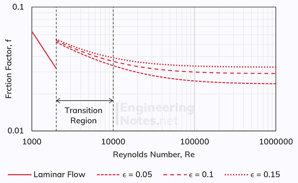
Where f is another dimensionless quantity: friction factor (sometimes called the Darcy friction factor).

The third and final dimensionless quantity is relative roughness, r. This is given as the ratio of the average height of wall roughness to diameter:

All three dimensionless quantities are related via the Moody Chart:
Minor Losses
Minor losses are much harder to calculate and need to be found empirically. They are caused by pipe bends, inlets/outlets, changes in cross-sectional area etc.
The minor losses are often greater than the major losses.
We can approximate the minor losses in terms of a component coefficient, k:

The constant k must be determined for the component in question. For example, a particular valve may have a coefficient of 0.001 or 7.
Pump Head
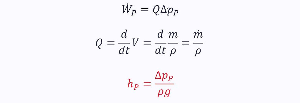
The pump head term in the pipe flow energy equation can be found in terms of the work output of the pump being used.

This can be expressed in terms of the pump work rate (or power):

Which is given as the pressure rise caused by the pump multiplied by the volumetric flow rate:

Comments