Hardness, Toughness, Creep & Fatigue
- Engineering

- Nov 29, 2020
- 4 min read
Hardness
The hardness of a material is its resistance to wear or indentation. It is generally measured using one of two types of indentation test.
Brinell Hardness

A 10 mm diameter steel sphere is pressed into the test material by a known force. This causes the sphere to leave a circular impression in the test material. The hardness is given by the following function of force, P, sphere diameter, D and impression diameter, d:

Vickers Hardness
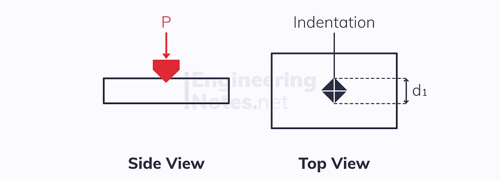
Instead of a sphere, a diamond shaped stud is used to indent the test material. The hardness is then calculated as a function of the force, P, and the diagonal of the square indentation, d₁:

Toughness
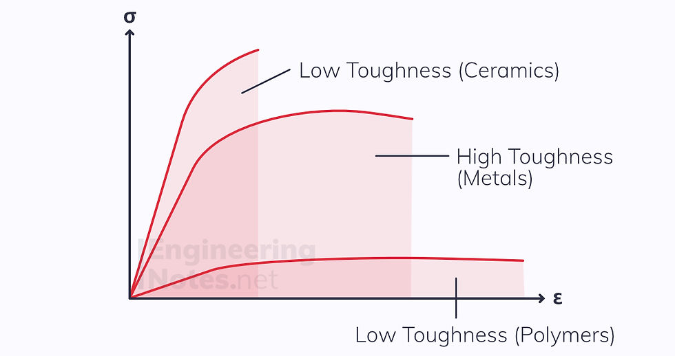
Toughness is related to a material’s ability to resist sudden, brittle fracture under a load. It is defined as the amount of energy needed for a material to fracture. Therefore, its units are Joules, J.
It is related to the area under a stress-strain curve, but is entirely separate to Young’s Modulus:
For fracture to occur, a crack needs to initiate somewhere and then propagate through the material. Often, the crack will initiate at a stress concentration like a screw hole or a bend. Fracture could be brittle or ductile.
Charpy Impact Test
The Charpy impact test is used to measure the toughness of a material.
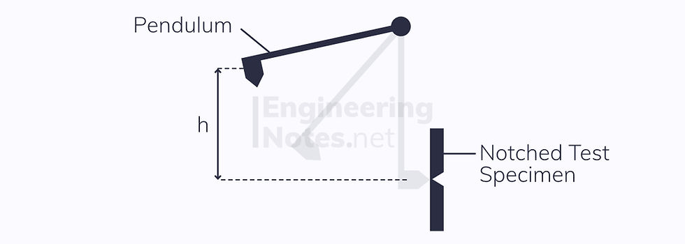
A heavy pendulum hits a notched test specimen, right opposite the notch.
The material fractures
The loss of potential energy of the pendulum (mgh) is calculated
The loss of potential energy of the pendulum is more or less equal to the energy required for the material to fracture, its toughness
There are a number of issues with this test, for example that energy is lost as heat, sound, kinetic energy etc – not all the GPE is transferred into fracturing the specimen.
Toughness and Temperature
The energy required for a material to fracture depends hugely on temperature. Generally, materials have a lower and upper ‘shelf’ of toughness. The graph below shows how the toughness varies with temperature of different carbon-content steels.
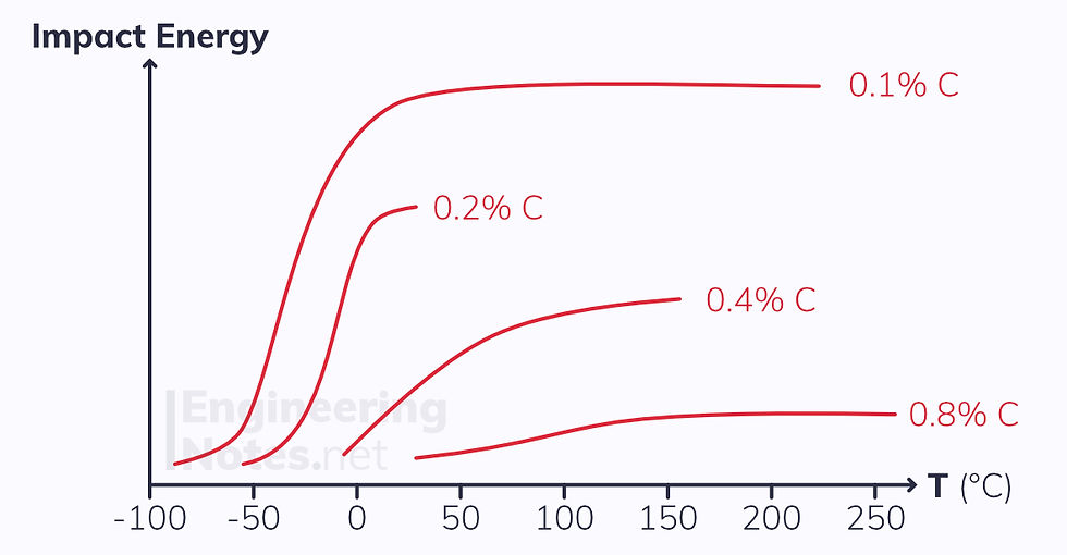
You can see that, generally, a higher carbon content increases the strength of steel, but decreases its toughness dramatically.
This is especially notable at room temperature (roughly 20 °C): high strength steels (0.8% C) have incredibly low toughness.
Creep
Creep is the way a material experiences an increase in strain over time (it extends). Stress is constant throughout.
At low temperatures, deformation of metals and ceramics is generally only dependent on stress, not time. At higher temperatures, this changes:

The sensitivity of a material to creeping is approximated by the ratio of temperature divided by melting point. Generally:
For polymers, creep is a problem when T > 20°C
For metals, creep is a problem when T > (0.3-0.4) x Melting T
For ceramics, creep is a problem when T > (0.4-0.5) x Melting T
Creep Curves
A creep curve is a graph of increasing strain as time goes on. Stress is assumed constant throughout:
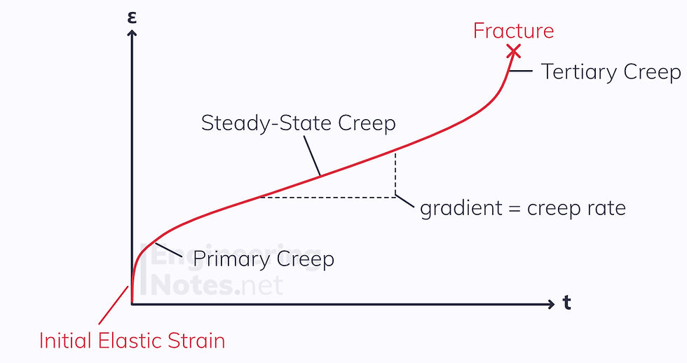
Generally, there are three creep phases between the elastic strain and fracture point: primary, steady-state and tertiary.
The steady-state creep rate is vital for calculating safe service life if the service life is expected to be very long. For shorter lifespans, the rupture lifetime (time before fracture occurs) is more important.
Creep Law
The creep law describes the relationship between steady-state creep rate, stress, and temperature:

A is a constant
Q is the activation energy for creep
R is the universal gas constant, 8.31
T is the temperature
σ is the stress
n is the creep exponent, also known as stress dependent
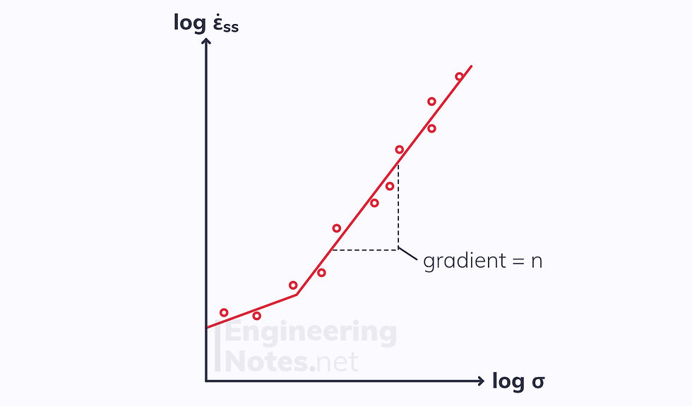
When temperature is constant, this reduces to:

Constants B and n can be found by plotting a logarithmic graph:
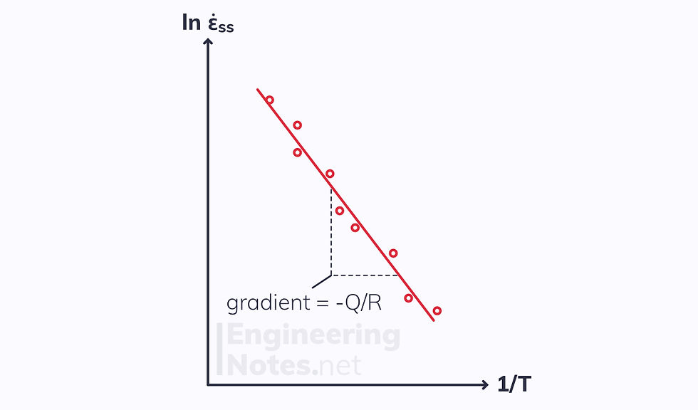
When stress is constant, the creep law becomes:

Plotting the natural logarithm of the creep rate and the reciprocal of the temperatures allows us to find C and -Q/R:
Fatigue
While stress is applied constantly in a creep scenario, in fatigue situations, the material experiences cyclical loading and unloading.
Fatigue is such a serious issue, because fracture can occur at stress levels significantly below the yield stress.
Fatigue stresses can be applied in many different ways. Three of the most common examples are:
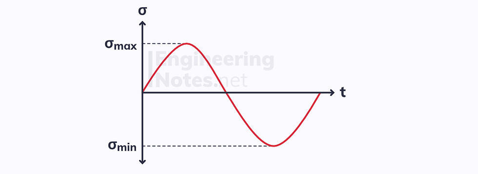
Fully reversed
The average stress is zero.
This is common in rotary shafts.
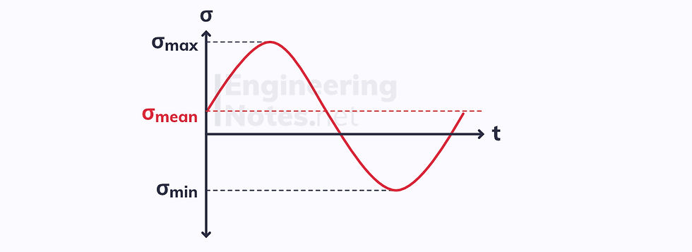
Tension-compressed
The mean stress is not zero
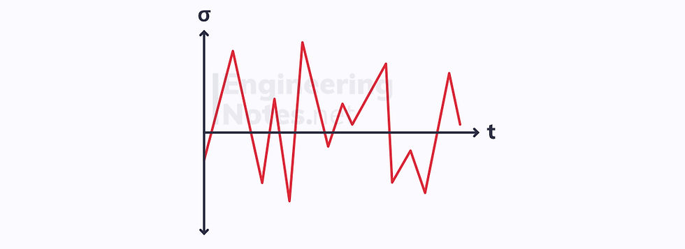
Random
There is no system or useful average.
This is common in suspensions where random shocks are common.
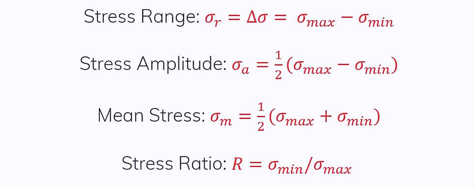
There are a number of important fatigue parameters:
Fatigue Cracks
Like any fatigue, the crack must first initiate somewhere and then propagate through the material. Once the remaining cross-section is no longer sufficient to carry the load, the material will experience a brittle fracture.
This could take anything from just a few to millions of cycles.
More often than not, the cracks initiate at stress concentrations, such as defects or design aspects (drill holes, sharp corners etc.).
It is easy to identify fatigue failure, as it leaves a distinct pattern of smooth slow crack growth around the epicentre, and rough brittle fracture marks everywhere else.
Fatigue Testing
In a fatigue test, a sinusoidal stress is applied to a test specimen and the number of cycles before fracture are recorded. Each experiment gives one datapoint, and so many iterations have to be done.
The results are then plotted on a scatter diagram:
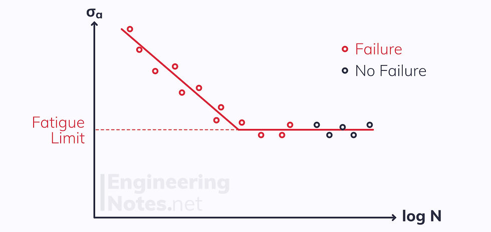
The above graph is typical for ferrous metals. As you can see, there is a fatigue limit: below this stress value, the specimen will not experience fatigue failure.
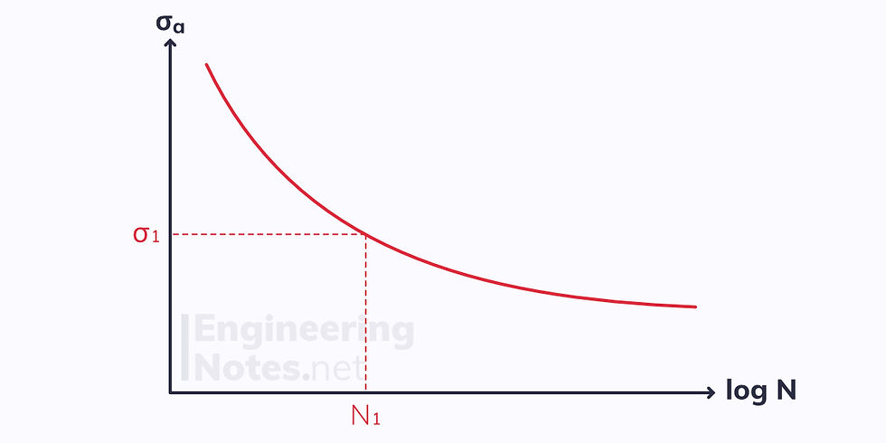
Other materials have a curved fatigue test scatter. There is no clear limit, and so there is no fixed stress value below which fatigue failure will not occur. Instead, we need to define either stress or number of cycles and read off the other.
Fatigue Safety Factors
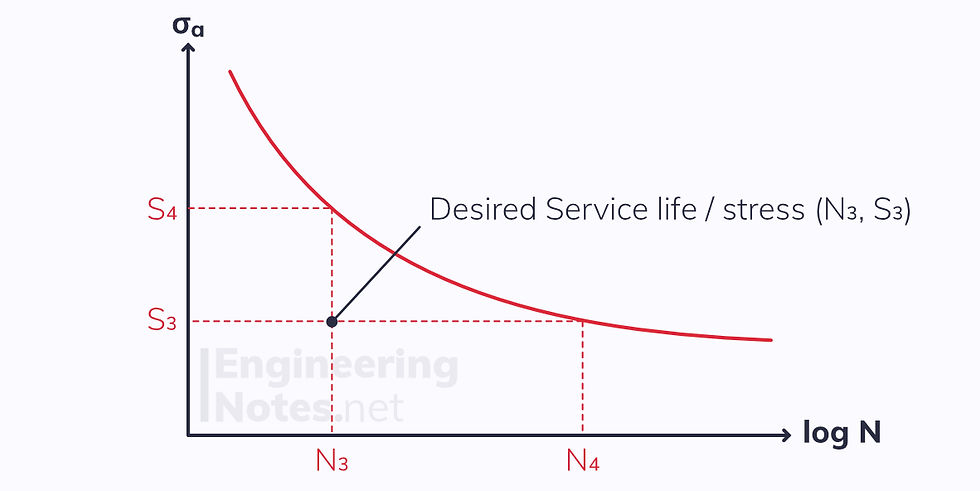
It is often important to calculate safety factors for fatigue strength or service life. For a given desired service life and stress amplitude (N₃, S₃), the safety factors are given as:

Summary
Hardness is a material’s resistance to wear or indentation
The two hardness tests are Brinell and Vickers
Toughness is the amount of energy required for a material to fracture
The Charpy Impact test investigates hardness
Toughness varies with temperature
Creep is when a material experiences an increase ins train over time
In low temperatures, creep depends only on stress
In high temperatures, creep depends on stress, temperature, and time
Fatigue failure occurs due to constant cyclical loading and unloading
Fatigue cracks tend to initiate at a stress concentration and propagate through the material
Ferrous metals have a fatigue limit – below this stress, fatigue failure will not occur

Comments