Circular Motion, SHM & Oscillations
- A-Level Physics

- Aug 5, 2020
- 5 min read
Updated: Dec 7, 2020
The S.I. unit for angles is not degrees, but radians. This is the angle subtended by a circular arc with a length equal to the radius of the circle:
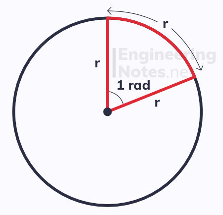
1 rad is equal to about 57.3°
There are 2π in a circle, and half that in a semicircle. Therefore,
to convert from degrees to radians, divide the angle in degrees by 180/π
to convert from radians to degrees, multiply the angle in radians by 180/π
Circular Motion
While the velocity of linear motion is defined as displacement / time, the velocity of circular motion is defined as angle / time. Therefore, it is called angular velocity, and is given the Greek letter omega, ω.
ω = θ/t angular velocity = angle / time
This equation is rarely used, however, as it is far easier to work with the time period and frequency of circular motion.
Time period, T, is the time taken for it to complete one circle.
Frequency, f, refers to the number of complete rotations (of 2π rads) per second.
This gives rise to the far more helpful equations:
ω = 2π/T angular velocity = 2π / time period
ω = 2πf angular velocity = 2π x frequency
The units of angular velocity are radians per second.
We can calculate the linear velocity using the angular velocity:
v = ωr linear velocity = angular velocity x radius
Centripetal Force
Even if the object undergoing circular motion is travelling at a constant speed, its velocity is always changing (due to its direction changing). This means the object is always accelerating – this is known as centripetal acceleration, and always acts towards the centre of the circle.
a = v²/r centripetal acceleration = linear velocity² / radius
a = ω²r centripetal acceleration = angular velocity² x radius
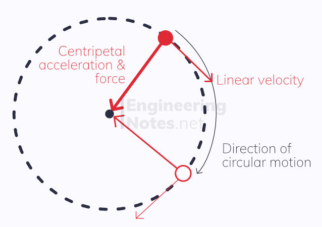
According to newton’s first law, if an object is accelerating, there must be a net force acting on it. This is the centripetal force, which is constantly acting perpendicular to the velocity, into the centre of the circle. This force is what causes the object to travel in a circular path.
From Newton’s second law (F = ma) we can derive:
F = mv²/r centripetal force = mass x velocity² / radius
F = mω²r centripetal force = mass x angular velocity² x radius
Despite the force constantly changing direction, the object’s velocity remains perpendicular. This means there is no motion in the direction of the force, and so no work is done on the object, and its kinetic energy remains the same.

Centripetal force can be investigated with a bung on the end of a string, a marker on it, a set of masses, and a glass tube.
Simple Harmonic Motion
All objects move slowly with simple harmonic motion (SHM) - either on an atomic scale (where the atoms in a solid vibrate) or on a larger scale like a spring or pendulum system. SHM is defined in terms of acceleration and displacement:
An object moving with SHM oscillates from side to side about a midpoint
Displacement is the distance from the midpoint
Amplitude is the maximum displacement (the furthest distance from the midpoint)
A restoring force constantly pushes or pulls the object back to the midpoint
The magnitude of the restoring force depends on the displacement and makes the object accelerate towards the centre
The period is the time taken to make one complete oscillation (from the midpoint out towards one side, back in through the midpoint and out to the other side, and back to the midpoint)
The frequency is how many complete oscillations are made each second.
It is important to note that frequency and period are independent of amplitude, because they are constant for any given oscillation.
Angular Frequency
Angular frequency, ω, is the magnitude of the vector quantity angular velocity in circular motion. Just like in circular motion, angular frequency is given by the following two equations:
ω = 2π/T angular frequency = 2π / time period
ω = 2πf angular frequency = 2π x frequency
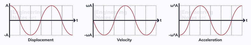
Acceleration
Simple harmonic Motion occurs when an oscillation’s acceleration is directly proportional to its displacement from the midpoint.
a = −ω²x acceleration = - (angular frequency)² x displacement
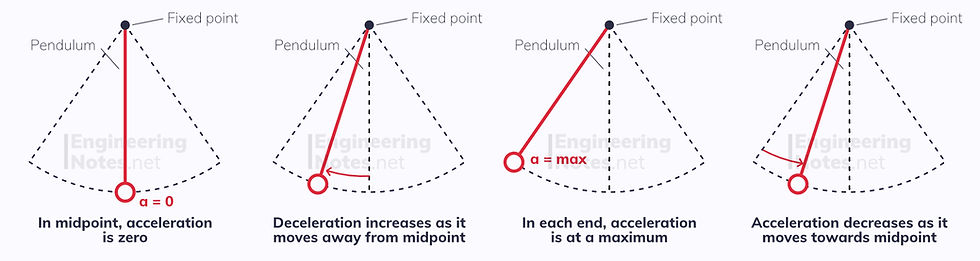
Acceleration always acts towards the midpoint, and is at a maximum at each end (where displacement = amplitude). As the object passes through the midpoint, its acceleration is zero.
a(max) = − ω²A maximum acceleration = - (angular frequency)² x amplitude
Velocity
The velocity changes depending on where in the oscillation the object is.
v = ± ω√(A² - x²) velocity = ± angular frequency x √(amplitude² - displacement²)
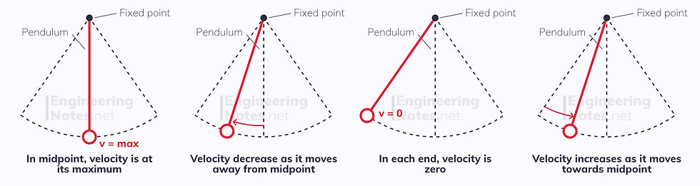
At each end, velocity is 0m/s (because it changes direction here). In the midpoint, velocity is at its maximum:
v(max) = ωA maximum velocity = angular frequency x amplitude
Displacement
Displacement varies with time, and is measured from the midpoint out.
If at t=0 seconds, the object is at its maximum displacement, use cosine:
x = A cos(ωt)
If at t=0 seconds, the object is in the midpoint, use sine:
x = A sin(ωt)
Displacement, Velocity & Acceleration Graphs
Phase Difference
Like waves, we use phase difference, ϕ, to denote the difference to compare two identical oscillations and the positions in their cycles.
If two identical oscillations both reach their maximum positive displacement at the same time, they are perfectly in phase with a phase difference of 0 rad.
If one reaches its maximum positive displacement when the other reaches its maximum negative displacement, they are exactly in antiphase with a difference of π rad.
Energy of Oscillations
When an object undergoes SHM, energy is constantly transferring from KE to GPE and back.
As the object moves towards its maximum amplitude, it gains height and as such GPE. This comes from a reduction in KE.
As the object returns to its midpoint, it loses GPE as this is transferred back into KE.
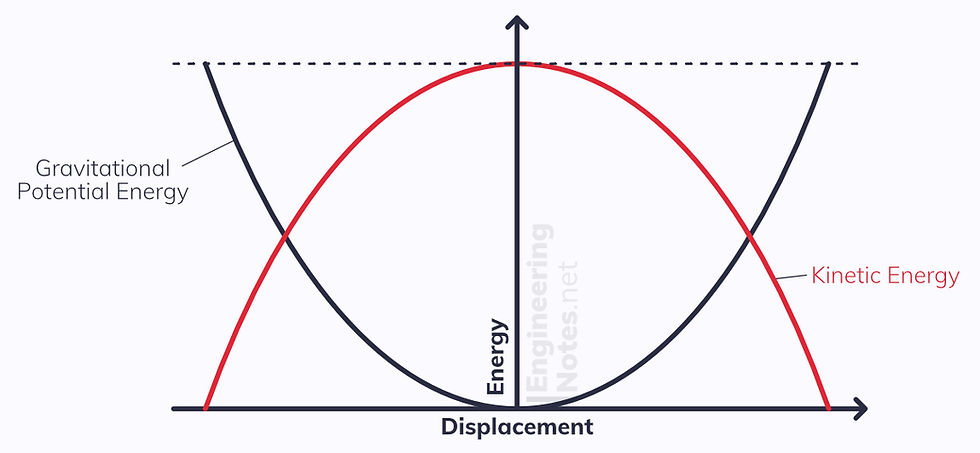
The maximum GPE is when KE is zero when the displacement is at its maximum.
The Maximum KE is when GPE is zero when the displacement is zero.
Resonance
Simple harmonic oscillations can either be free or forced.
Free oscillations have no transfer of energy to or from their surroundings. For example, if a mass on a spring that has been pulled down and released has no external factors, it will oscillate at its natural frequency at the same amplitude forever. In reality, this never happens because factors like air resistance reduce the amplitude dramatically.
Forced oscillations happen when there is an external driving force, at a set driving frequency. This inputs energy to the system.
All substances, systems and structures have a natural frequency. This is the frequency at which they oscillate freely.
Resonance
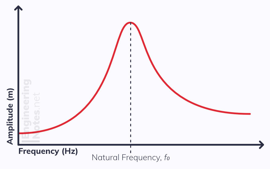
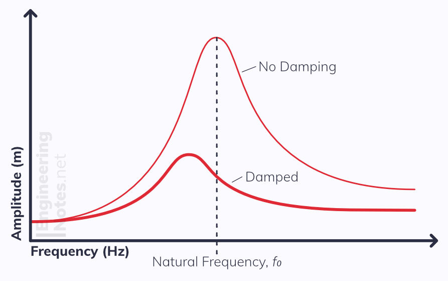
If the driving frequency is equal to the natural frequency, resonance occurs. This is when the system gains more and more energy from the driving force, and so the amplitude quickly increases. Sometimes, this can be strong enough to destroy the system entirely.
Damping
The forces that oppose SHM are known as dampening forces. The most common example is air resistance. Systems are often deliberately damped to stop them oscillating or minimise effects of resonance.
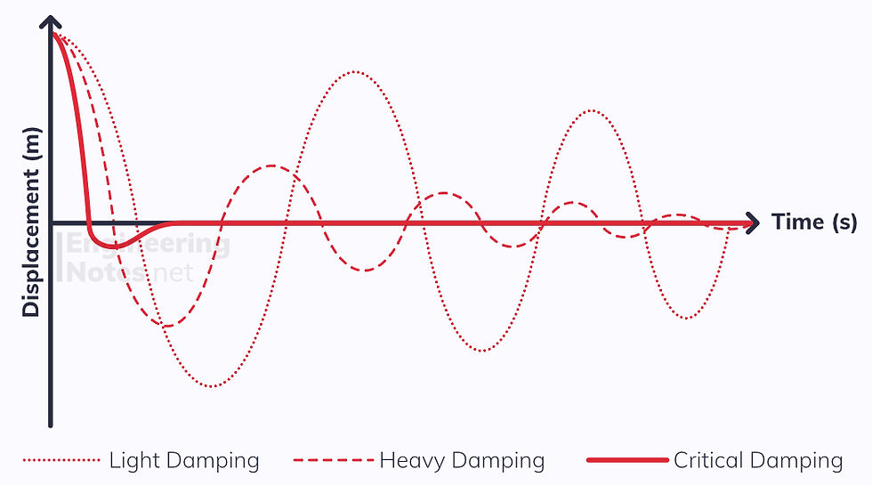
The heavier the damping, the faster the amplitude decreases – however it always happens at an inverse square rate.
Light Damping reduces the amplitude by a very small amount each time.
Heavy Damping reduces the amplitude quickly, and within a few cycles, the oscillations become negligible.
Critical damping is when it never oscillates: the amplitude is reduced in the shortest possible time.
Damping affects resonance and the natural frequency as well:


Comments