Electrical Circuits
- A-Level Physics

- Aug 5, 2020
- 3 min read
Updated: Dec 7, 2020
First off, a recap of Kirchhoff's laws:
Kirchhoff's 1st Law
Since charge is conserved in a circuit, none can be lost at path junctions. The rate of flow of this charge is also unchanged, meaning the total current going into a branch equals the total current coming out of the branch, regardless of how many points are on the branch.
Current/charge is conserved around a circuit – when the current reaches a branch it splits so that the total current in the branches is equal to the current before splitting.
Kirchhoff's 2nd Law
This law applies the principle of conservation of energy to electrical circuits. It says that the amount of energy being put into the circuit (the E.M.F.) must equal the amount of energy coming out of the circuit (the P.D.):
Electrical energy is conserved in a circuit - the sum of the e.m.f.s around any closed loop equals the sum of the p.d.s around the closed loop.
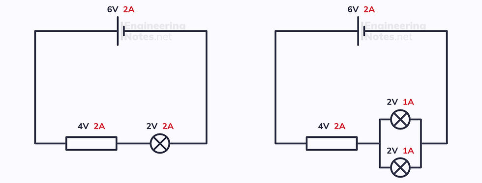
Practically, these laws mean that in series, the voltage across all components adds up to the supply voltage and the current is the same across each component, while in parallel, the total voltage in each branch is the same and the current in the branches add up to the pre-branching current.
Resistors in Circuits
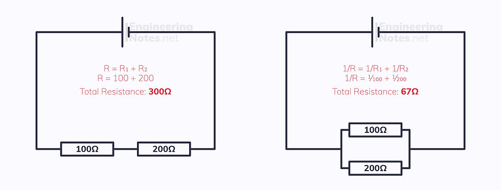
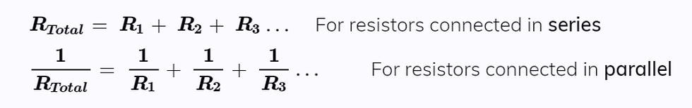
The layout of resistors in a circuit makes a big difference. In Series, the values of the resistors are just added together to find the total resistance. In parallel, however, the sum of one over each resistance value gives one over the total resistance.
Internal Resistance
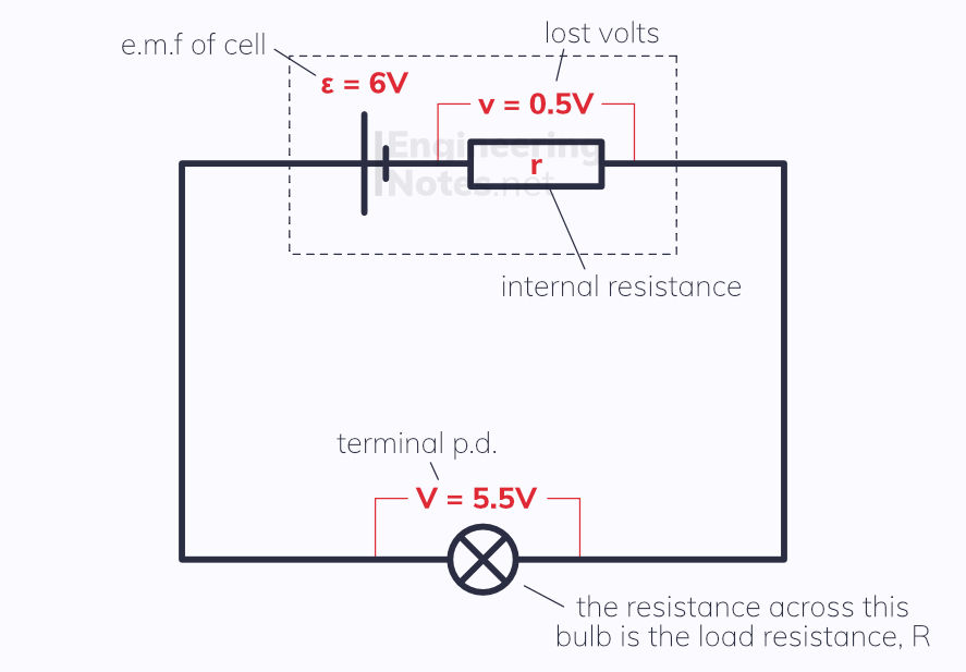
All sources of e.m.f. have internal resistance, because the electrons collide with the atoms inside the power supply – this is what causes them to warm up.
The terminal p.d. is the voltage used in the circuit, or the p.d. across the load resistance, R. If there was no internal resistance, the terminal p.d. would equal the e.m.f. of the supply. The energy wasted per coulomb of charge in overcoming the internal resistance is known as the lost volts, v.
There are three equations associated with internal resistance:
ε=V+v e.m.f. = terminal p.d. + lost volts
ε=I(R+r) e.m.f. = current (load resistance+internal resistance)
ε=V+Ir e.m.f. = terminal p.d. + (current × internal resistance)
It is easiest to think of internal resistance as a normal resistor connected in series with the power supply and then use normal electricity laws and equations to work things out.
Investigating Internal Resistance
ε = V + Ir rearranges to V = −Ir + ε, the equation of a straight line (y = mx + c). This can be used experimentally to work out internal resistance:
measure the terminal p.d. and current in the circuit as you vary the load resistance
plot these on a graph of V against I
The gradient will be the internal resistance and the y-intercept the e.m.f.
Additionally, putting a voltmeter at either end of an e.m.f. source will tell you a value very slightly smaller than its e.m.f., as voltmeters have a very high resistance but a small current still passes through.
Good to know:
When the circuit is open, and no current is drawn, the e.m.f. equals the terminal p.d.
When the circuit is shorted, the terminal p.d. is 0 and the e.m.f. is at a maximum.
Potential Dividers
Potential dividers are amongst the most common circuit types, because they have the simple but crucial ability to vary the p.d. across an output when connected to a fixed input.
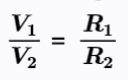
Potential dividers consist of two or more resistors are connected in series so that the voltage is split across them to add up to the e.m.f. The p.d. is divided in the ratio of resistances:
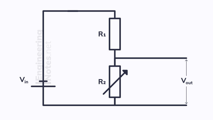

Potential dividers can be used to produce a varying output voltage, either manually with a variable resistor or automatically with an LDR or thermistor. The diagram above shows a variable resistor.
As the resistance across R2 changes, so does the ratio of resistances (because R1 has a fixed resistance). This means the voltage across each resistor also changes. The higher the resistance on R2, the higher the output voltage.
Potentiometers
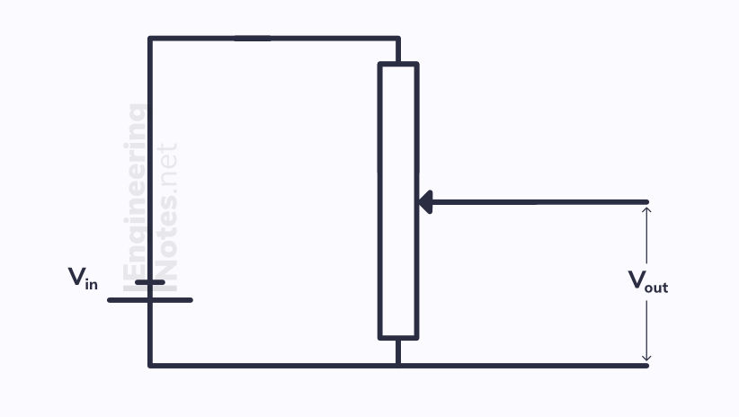
A potentiometer is a variable resistor with three terminals – it s essentially a normal potential divider, but the two resistors are combined into one variable resistor. As the contact moves towards the top, the ratio of resistances changes the output p.d. increases. As the contact moves down, the output p.d. decreases. At the top, Vout = Vin, whereas at the bottom, Vout = 0. Potentiometers are used for volume control, dimmer switches etc.


Comments