Magnetism & Electromagnetism
- A-Level Physics

- Aug 5, 2020
- 5 min read
Updated: Dec 7, 2020
A magnetic field is a region in which a magnetic material experiences a force, and is caused by a moving charge or a permanent magnet.
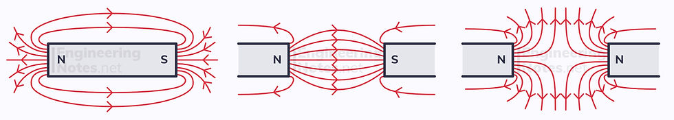
Just like gravitational and electric fields, magnetic fields are represented by field lines - except instead of talking about positive and negative end, we talk about north and south poles. The closer the field lines, the stronger the magnetic field. Identical to charges, like poles repel and opposite poles attract.
The diagram above shows the field patterns from permanent bar magnets, but magnetic fields arise all the time from current-carrying wires:

For a straight current-carrying wire, the field lines are arranged in concentric circles in a plane perpendicular to the wire and direction of current. This is found using the right-hand grip rule.
A flat current-carrying coil produces the same pattern, but all the way around the coil, so the field is three-dimensional.
A solenoid produces this pattern on an elongated scale.
Magnetic Flux Density
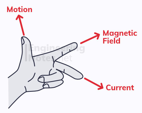
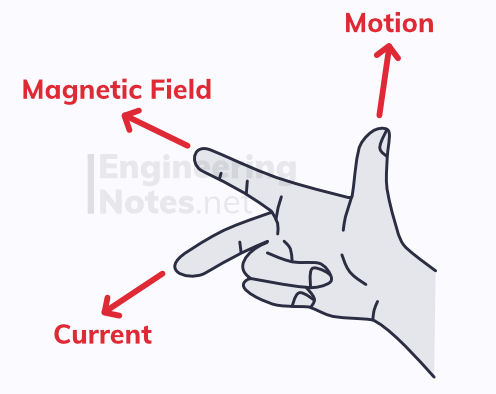
A current that is perpendicular to a uniform magnetic field will induce a force. The direction of this force can be established with Fleming's left-hand rule:
The magnitude of the force causing the motion is proportional to the magnetic flux density, B, of the magnetic field. This is defined as the force on one meter of wire carrying a current of 1 amp, perpendicular to the magnetic field.
F = BIL sinθ Force = flux density x current x length of wire x sin(angle with magnetic field)
If the wire is perpendicular, the equation is just F = BIL, as sin(90°) = 1
If the wire is parallel, there is no force, as sin(0°) = 0
This relationship can be investigated with a known length of wire on a scale, running perpendicular through a uniform magnetic field. When a known current passes through the wire, the scale will read a change in mass. This, multiplied by g, is equivalent to the force exerted on the wire.
The units of magnetic flux density are Tesla, T, defined as 1Wb/m (see electromagnetism, below)
Motion of Charged Particles
F = BIL is the equation used for calculating the force on a current-carrying wire perpendicular to a uniform magnetic field. This is not to be confused with the following equation, used for charged particles perpendicular to a uniform magnetic field:
F = BQv Force = flux density x charge x velocity
Circular Motion
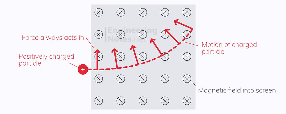
According to Fleming's left hand rule, the motion of a charged particle must always be perpendicular to its motion. This means that the articles will travel on a curved or circular path, as the force induced acts as a centripetal force:
Velocity Selectors
A velocity selector is a device that makes use of electric and magnetic fields to produce a fine stream of particles at a given velocity. The two fields are perpendicular to one another, and the particles are charged before entering the device.
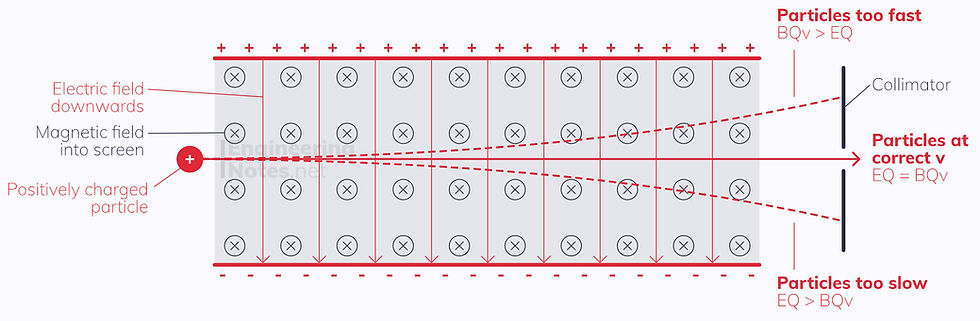
The particles will experience an upwards force from the magnetic field, according to Fleming's left hand rule, of magnitude BQv.
The particles experience a downward force from the electric field, because the positive charge of the particle is attracted to the negative end of the field. The magnitude of this force is given as EQ.
Unless the upwards and downwards forces are the same, the particle will experience a resultant force and be deflected.
Therefore, only particles where BQv = EQ will continue in a straight line. The charges cancel, so the selected velocity is given as:
v = E/B selected velocity = electric field strength / flux density
This is used in mass spectrometers to identify ions and particles, based on their mass.
Electromagnetism
Magnetic flux, ϕ, is defined as the product of the perpendicular component of the flux density through a given area. More or less, this means the number of field lines passing through a particular area. It is calculated as:
ϕ = BA cosθ magnetic flux = flux density x area x cosθ
Magnetic flux linkage, Nϕ, is the product of the flux, ϕ, and the number of coils, N.
ϕ = BAN cosθ magnetic flux linkage = flux density x area x number of coils x cosθ
Both flux and flux linkage have Weber, Wb, as their units. However, to avoid confusion, Weber Turns are sometimes used as the units for flux linkage.
Electromagnetic Induction
When a conductor moves through a magnetic field and experiences a change in magnetic flux, an e.m.f. is induced. This happens because the electrons in the conductor move to one side of it, according to Fleming's left-hand rule. This leads to a resultant positive charge on the opposite side.
Faraday's Law
Faraday's Law states that the magnitude of e.m.f. induced is directly proportional to the rate of change of magnetic flux linkage:
ε = -Δ(Nϕ) / Δt e.m.f. = - change in magnetic flux linkage / change in time.
ε = -Δ(BAN cosθ) / Δt (using the equation for flux linkage above)
Lenz's Law
Lenz's law states that the direction of the induced e.m.f opposes that of the change in flux that has taken place. This is why Faraday's law above has a negative sign in it.
A.C. Motors & Generators
A.C. Motor
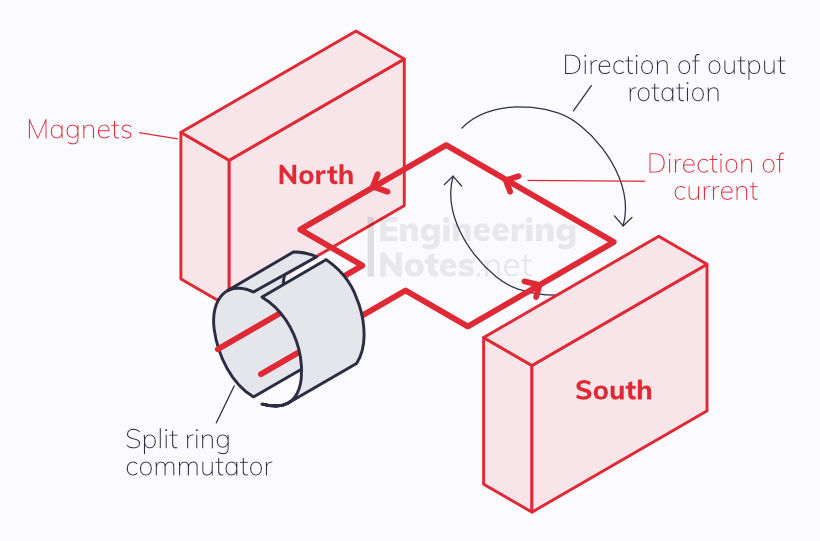
In the setup above, when a current passes through the red wire rectangle, it moves clockwise. This is because, according the Fleming's left hand rule, the motion, magnetic field, and current must all by perpendicular. There is a split ring commutator to change the direction of current every half turn - else the motor would always change direction.
To increase the speed, the current, magnetic field strength, or number of coils should be increased.
A.C. Generator
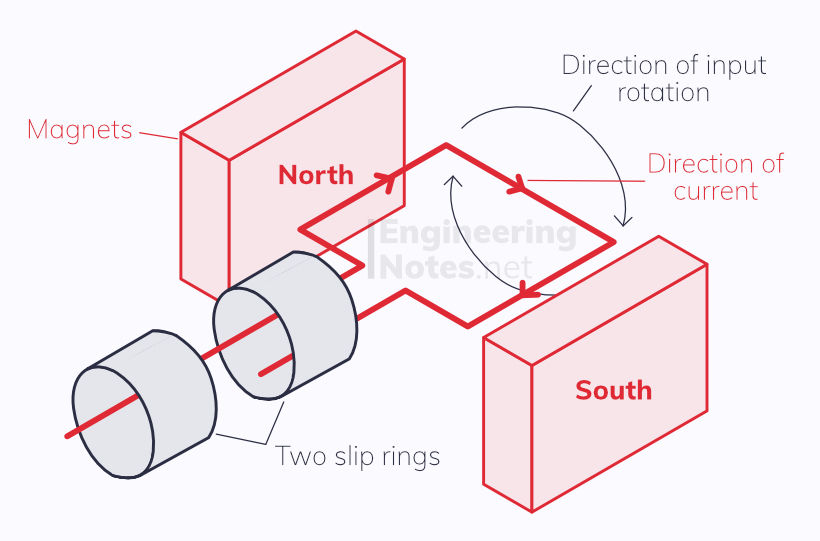
For a generator, we sue the right hand rule instead. Each finger still represents the same thing. Note that the current in the rectangular wire coil is going the opposite way to in the motor, and that there are two slip rings instead of a split ring commutator - this is why the current provided is alternating.
The e.m.f is induced because of the change in magnetic flux experienced by the wire coil as it rotates. Therefore, faster rotations cause a higher current. This can also be achieved by more coils or stronger magnets.
Transformers
Transformers are made up of a laminated soft iron core with at least two wire coils on it, the primary and secondary. When an AC current is applied to the primary coil, a constantly changing magnetic flux is induced in the iron core. This, in turn, induces an e.m.f. in the secondary coil.
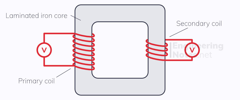
An iron core is used because it is so easily and efficiently magnetised and demagnetised. This ensures that, even though the transformers produce a large amount of heat, all the magnetic flux produced by the first coil is transferred to the second. The core is laminated (meaning it is made up of many very thin insulated layers) to prevent losing to much heat from induced currents in the core itself - these are known as eddy currents.
For an ideal transformer, we can use the turn-ratio equation to calculate the output voltage:
n(s) / n(p) = V(s) / V(p) primary coils / secondary coils = primary voltage / secondary voltage
Assuming the transformer is 100% efficient, we can assume that power is conserved. Therefore, since P=IV, we can assume that
V(p) x I(p) = V(s) x I(s) Primary voltage current = secondary voltage x current
Therefore, we can see, that if voltage is stepped up, then current must step down and vice versa.
Step-up transformers increase voltage and decrease current
Step-down transformers decrease voltage and increase current


Comments